


We manufacture and deliver steel prefabricated halls more than 20 years. We always try to find an optimal functional and architectural solution for the creation of the unique work of art.
We draw from the experience acquired from more than 1000 of our completed construction works.
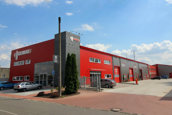
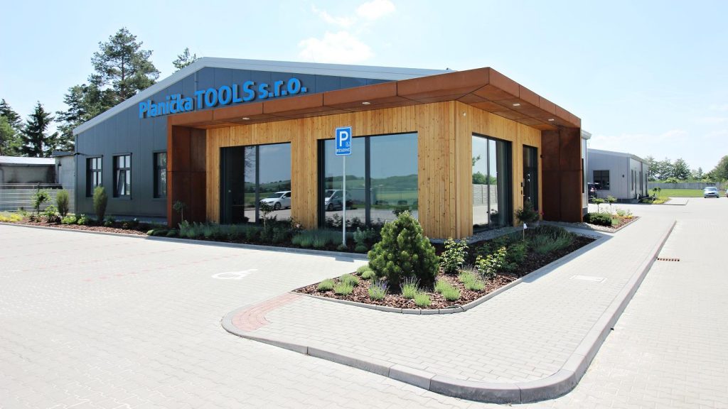
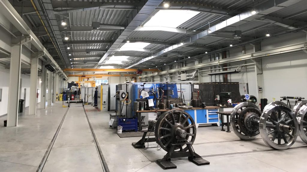
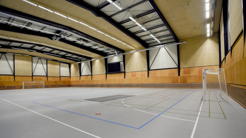
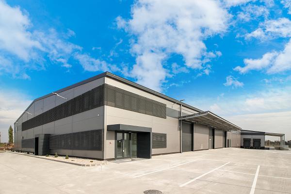
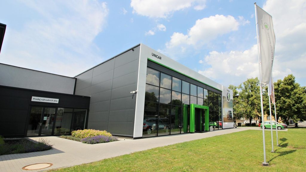
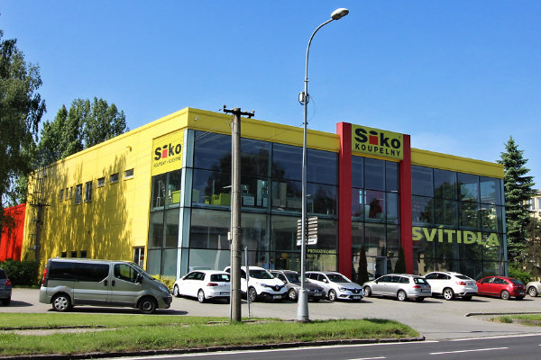
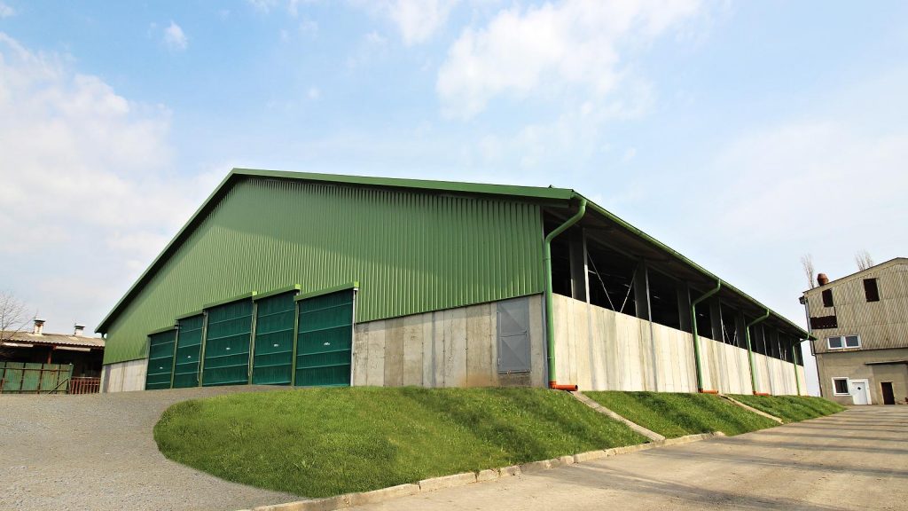
Thanks to flexible design solution are our halls found in many sectors from industry, agriculture to storage, sport or development of urban infrastructure.
We think of the future of your company. We will be happy if, you think of us in the future, too.
Advantages over the systems
- No wet process
- Fast and flexible installation
- A wide range of wall and roof systems
- Lean and aesthetic design
- Creative freedom when designing the structure of slim and aesthetic design
- High precision of components with minimal tolerances
- A high proportion of workshop production, quality is assured with certified processes
- The possibility of the realization even in the winter months